Part 2 of door family modification-
Now we're going to take out a couple of reference planes that constrain the necessary resizing of the door. Sometimes it's easier to take them out and redraw than to unravel multiple constraints. Really two doors, the 3D version and the plan version (detail object). These are set 2" off the rough opening work planes, select and delete:
Grab the door panel extrusion and stretch the jambs to align with the frame jambs. Next constrain each door jamb by clicking on the alignment constraint (the little lock):
That takes care of the 3D part of the door. [Note: It's often best to create reference planes for constraint rather than constraining geometry-to-geometry. "So far" I haven't had a problem without them when the plane would just be sandwiched between geometry.] The panel will size automatically when Width, Height, Panel Width, or Panel Height are changed in the Family Type parameters. A couple examples in 3D:
But back to 2D- the Door-Swing detail item represents the door in plan view. At the moment it resizes correctly but is off-center. There's already a 2" dimension on the hinge side. It turns blue when the door is highlighted, which means it's associated with the door. Manually edit it to 1" and the door will move to center. Lock down the constraint:
Save the door, it's finally done! Well, mine's done, anyway, let me know if it worked for you. And don't worry even one second about the constraints and work planes that were blown off; perhaps families can become over-constrained during the process of creation.
Tuesday, March 30, 2010
Monday, March 29, 2010
How to modify a door family - Part 1
This is Part 1 of a hack to modify an existing door family to more accurately match actual construction. The results appear to work but are not rigorously tested, so make a backup first.
Door families with hollow-metal frames are out there, but haven't come across one that creates a rough opening correctly out-of-the-box. Example using one of the doors downloaded from Reed Construction's SmartBIM: Probably any of Reed's flush doors with a hollow-metal frame will do; I'll be looking at 'Door_Single_Glazed-1-Lite_Reed'. We're ahead of the game here already compared to Revit's default doors because it's a complete frame, not just trim that only appears in 3D. Both doors pictured are 3'0. The 'before' door is cutting a 3'4 rough opening. What's needed is a 3'2 R.O. per 'after'.
Door families with hollow-metal frames are out there, but haven't come across one that creates a rough opening correctly out-of-the-box. Example using one of the doors downloaded from Reed Construction's SmartBIM:
 Probably any of Reed's flush doors with a hollow-metal frame will do; I'll be looking at 'Door_Single_Glazed-1-Lite_Reed'. We're ahead of the game here already compared to Revit's default doors because it's a complete frame, not just trim that only appears in 3D. Both doors pictured are 3'0. The 'before' door is cutting a 3'4 rough opening. What's needed is a 3'2 R.O. per 'after'.
Open the door in the family editor and go to the Ref.Level view. Selecting items reveals a network of constraints. Of the various ways to revise the family, it seems that altering the frame sweep profile affects
the fewest constraints. Select the door frame and choose Edit Sweep-> Select Profile-> Edit Profile from the ribbon bar. Should see something like this: Select all the lines and arcs that make up the frame and move them 1" to the right. About five "constraints are not satisfied" errors will result. Hit Remove Constraints, Finish Profile, and Finish Sweep. Another "constraints are not satisfied" may appear, so again hit Remove Constraints. We'll get back to tidying the necessary constraints.
The hollow metal frame overlaps the wall an inch, good, but now the door panel is too narrow for the opening. Likewise the detail item (plan view swing) is too small. Hit Types on the ribbon bar, scroll down to the Dimensions heading within the Family Types dialog, and change the height and width. It's probably 7'-2" and 3'-4". Change it to 7'-1" and 3'-2", the rough opening size for a standard 3' x 7' door frame. Now scroll down further for the truly sneaky but elegant part... under the "Other" heading are the formulas for the door panel size. Originally it's subtracting 2" all around but should be 1". Change the formulas to match the following:
Hit OK... part 2 to follow.
Labels:
door family,
door frames,
Revit
Facing a BIM software decision? Content is king.
From the perspective a small studio doing design build architecture, the availability of ready-made BIM components was a major factor in the choice of software. It was soon apparent that the parametric parts of existing AutoCAD Architecture libraries would not translate into either Revit or ArchiCAD. We even looked at Chief Architect for its excellent cabinet layout integration and other features possibly suitable for light commercial construction. But Revit families have become the standard format for (USA) manufacturers, and that fact won out over differences in features or workflow. In fact, the quantity and variety of Revit families is amazing compared to the limited availability of items for AutoCAD Architecture.
Places to get Revit families:
Reed Construction Data SmartBIM - Professionally made families of consistent quality. The highly-detailed space layouts are great examples. Also check out their SmartBIM Library product for organization of Revit objects.
RevitCity - Huge variety of varying quality user-uploaded content, available with registration. A good place to start when looking for specialty items.
Autodesk Seek - This is the search site built-in to Revit, a growing library of manufacturer objects.
ARCAT Free BIM Library - A large number of generic objects. Does not include manufacturer BIM objects, which may be found with product search.
Friday, March 26, 2010
Migrating hatch patterns from AutoCAD to Revit
Here's one way to migrate hatch patterns from AutoCAD to Revit-
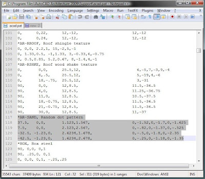
Open acad.pat in a text editor, maybe a good tabbed text editor like Notepad++, and highlight the desired pattern. It will look something like:

Copy-paste the highlighted pattern into a new text file. Add a new line at the bottom to tell Revit what type of pattern it is.
;%TYPE=MODEL
or
;%TYPE=DRAFTING
Save the file as "somename.pat" and import it as the desired pattern type, model or drafting. How to import? Straight out of Revit 2010 help:
Creating a Custom Fill Pattern
Open acad.pat in a text editor, maybe a good tabbed text editor like Notepad++, and highlight the desired pattern. It will look something like:

Copy-paste the highlighted pattern into a new text file. Add a new line at the bottom to tell Revit what type of pattern it is.
;%TYPE=MODEL
or
;%TYPE=DRAFTING
Save the file as "somename.pat" and import it as the desired pattern type, model or drafting. How to import? Straight out of Revit 2010 help:
Creating a Custom Fill Pattern
- Click Manage tab->Project Settings panel->Settings drop-down->Fill Patterns.
- In the Fill Patterns dialog, under Pattern Type, select Drafting or Model.
- Click New.
- If you are creating a drafting fill pattern, select how to orient the fill pattern in the host layers. See Fill Pattern Host Orientation for details.
- In the New Pattern dialog, select Custom.
- Click Import.
- Select the desired pattern file (PAT), and click Open. See Custom Pattern Files for information on creating a custom pattern (PAT) file.
- NoteDefault Revit Architecture fill patterns are stored in the revit.pat and revit metric.pat files in the Revit Architecture program group Data directory. The revit metric.pat file contains various metric masonry and iso patterns.
- Click the menu next to Import to view the list of available patterns. Select a pattern from the list.
- If desired, enter a new name for Name.
- If desired, enter a value for Import scale.
- Click OK twice.
Labels:
AutoCAD,
fill pattern,
hatch pattern,
Revit
Revit temporary dimension settings

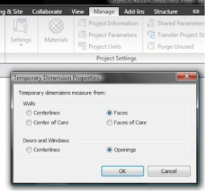
By default, Revit shows a temporary dimension from centerline of wall to center of opening when placing doors. To change that to wall face and edge of opening, go to the Manage tab-> Settings -> Temporary dimensions:
A temporary override would be handy while placing items. I wonder if behavior has changed in 2011?
Labels:
Revit 2010,
temporary dimensions
Subscribe to:
Comments (Atom)


