Showing posts with label door frames. Show all posts

Tuesday, March 30, 2010

How to modify a door family - Part 2

Part 2 of door family modification-
Now we're going to take out a couple of reference planes that constrain the necessary resizing of the door.  Sometimes it's easier to take them out and redraw than to unravel multiple constraints.  Really two doors, the 3D version and the plan version (detail object).  These are set 2" off the rough opening work planes, select and delete:

Grab the door panel extrusion and stretch the jambs to align with the frame jambs.  Next constrain each door jamb by clicking on the alignment constraint (the little lock):


That takes care of the 3D part of the door.  [Note: It's often best to create reference planes for constraint rather than constraining geometry-to-geometry.  "So far" I haven't had a problem without them when the plane would just be sandwiched between geometry.]  The panel will size automatically when Width, Height, Panel Width, or Panel Height are changed in the Family Type parameters.  A couple examples in 3D:


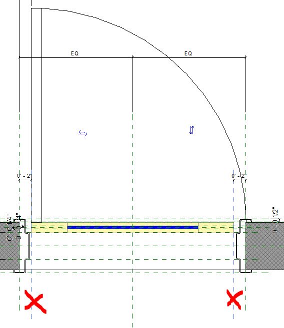
But back to 2D- the Door-Swing detail item represents the door in plan view.  At the moment it resizes correctly but is off-center.  There's already a 2" dimension on the hinge side.  It turns blue when the door is highlighted, which means it's associated with the door.  Manually edit it to 1" and the door will move to center.  Lock down the constraint:


Save the door, it's finally done!  Well, mine's done, anyway, let me know if it worked for you.  And don't worry even one second about the constraints and work planes that were blown off;  perhaps families can become over-constrained during the process of creation.


Monday, March 29, 2010

How to modify a door family - Part 1

This is Part 1 of a hack to modify an existing door family to more accurately match actual construction.  The results appear to work but are not rigorously tested, so make a backup first.

Door families with hollow-metal frames are out there, but haven't come across one that creates a rough opening correctly out-of-the-box. Example using one of the doors downloaded from Reed Construction's SmartBIM: Probably any of Reed's flush doors with a hollow-metal frame will do; I'll be looking at 'Door_Single_Glazed-1-Lite_Reed'. We're ahead of the game here already compared to Revit's default doors because it's a complete frame, not just trim that only appears in 3D. Both doors pictured are 3'0. The 'before' door is cutting a 3'4 rough opening. What's needed is a 3'2 R.O. per 'after'.
 
Open the door in the family editor and go to the Ref.Level view. Selecting items reveals a network of constraints. Of the various ways to revise the family, it seems that altering the frame sweep profile affects
the fewest constraints. Select the door frame and choose Edit Sweep-> Select Profile-> Edit Profile from the ribbon bar. Should see something like this:Select all the lines and arcs that make up the frame and move them 1" to the right. About five "constraints are not satisfied" errors will result. Hit Remove Constraints, Finish Profile, and Finish Sweep. Another "constraints are not satisfied" may appear, so again hit Remove Constraints. We'll get back to tidying the necessary constraints.

The hollow metal frame overlaps the wall an inch, good, but now the door panel is too narrow for the opening. Likewise the detail item (plan view swing) is too small. Hit Types on the ribbon bar, scroll down to the Dimensions heading within the Family Types dialog, and change the height and width. It's probably 7'-2" and 3'-4". Change it to 7'-1" and 3'-2", the rough opening size for a standard 3' x 7' door frame. Now scroll down further for the truly sneaky but elegant part... under the "Other" heading are the formulas for the door panel size. Originally it's subtracting 2" all around but should be 1". Change the formulas to match the following:


Hit OK... part 2 to follow.